
Roger440
-
Posts
165 -
Joined
-
Last visited
Content Type
Profiles
Forums
Calendar
Gallery
Everything posted by Roger440
-
750ml is a fair bit. Topping it up won't cause a problem, other than the slight change of protection, though longterm i would correct this to avoid any corrosion issues. As already stated, i think you really need to know where it has gone. Do you know over what period it has gone missing?
-
I'l sort something out for you Tony. Might be a few days, its a bit manic at the moment - im surrounded by broken engines!!
-
Right, i have had a bath and a doodle on my note pad (all the best ideas happen here) and by my reckoning, if the rack is located behind the axle line, moving the rack rearwards would achive your objective. As a consequence, moving the TRE forward should have the same effect. I should probably patent my idea!!, but my initial thoughts are a bracket thats utilises the existing tapered hole to secure the bracket to the steering arm, call it what you will. Attached to this bracket would be a bolt/threaded bar with lock nuts, which would clamp a rose joint screwed to the end of the track rod. The rose joint could then be adjusted fore aft and locked in the correct position. Not a great description i know, a drawing would be preferable. Couple of potential flaws however! It relies on the taper to hold solid under turning forces. A taper (morse) should be capable of transmitting large rotational forces, but i don't know if its size is large enough in this application. I have also assumed that the rose joint is capable of enough angle to allow this to work. Could be mounted the other way, but this then would involve a clamping arrangemet to prevent movement after adjustment. I dreamed up this idea because it would not be vehicle specific. A couple of variations in size could cover a multitude of vehicles. Are you able to work out in mm how far you would need to move the joint on a typical application to achive the objective?
-
The steering rack position and the direction of the TRE curvature determines the TOOT, as the steering arm is retracted on the inner wheel then the curvature generates a disparity in the pivotal point, whereas the extension outer wheel is belayed most of the disparity. I am disinterested on the suspension construction only the steering construction, if the steering configuration supports the design suggested then i feel manipulation of the curvature welcomes some consideration. STOP! What do we mean by TRE curvature? Are we talking its physical shape, or its travel (arc?)? A curve in the arm will make no difference. You can put as many curves as you like in a bar between 2 points, but the arc that it strikes will be the same, dictated by the pivot point at each end. Are we talking cross purposes?
-
If moving the rack, practical difficulties aside, achieves the aim, then my idea of moving the track rod must surely work? I feel a design forming! "cars that use the hub with an off-set catchment for the TRE could not play a part in this evolution " Not sure i understand that. Would the idea work on a conventional McPherson strut set up with single lower ball joint? Having thought about it further, i still don't see how altering the bend in the example you posted changes the TOOT. One end or the other of the track rod has to have its position altered. Shame, because i feel that making such a device could be achieved.
-
I think im with you. 2 questions that would clarify it for me. My orginal question, moving the rack fore / aft would achive the objective? If you could move the ball joint on the track rod fore and aft on the steering arm this too would work, ie adjustable? (leaving the practicalities aside) Put another way, its the relationship between the pivot point at the rack and the ball joint at the steering arm in a fore/aft plane . the further "out of line" these 2 piints are the greater the TOOT. (if done in the right direction of course) I could do a sketch on paper, but we can't do that here The bend itself is merely a means of achieving the objective of altering the relationship? One more! Is this going to work on a conventional set up? Ie not the one you have shown with the double ball joint arrangement at the bottom of the strut.
-
Surely though, bending the track rod is the same as adjusting it? Its overall length will change. Are we actually talking about the same bit of equipment?
-
Just so i can get this clear in my mind, if you were to take the move the rack route, in which plane would you move it? Fore/aft? Im struggling to see how bending the arm (track rod?) changes anything. If the pivot points are still in the same place, surely the geo stays the same?
-
Correct me if i'm wrong, but if you could move the outer end of the steering arm up or down then this would achive the objective, albeit the radii may not be perfect? Steeda in America do a device, the details of which escape me at the moment, that effectively allows this to be done. Its prime purpose as sold is to reduce the effects of bumpsteer on very low cars, but may be able to achieve your objective?
-
Ok, i'll see if i can dig something out for you all. And i got the picture to work too By way of celebration i'll post another.
-
-
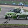
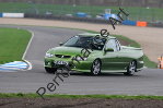
Ok, ill give it a go. I reckon the car pulls to the left and the steering is to the right? Don't buy the car though, i think its taken a knock to the front O/S I'll try the piccy thing too.
-
Due to the spammers you will need an external link.... Photo bucket is a popular route. This is how to to do it....once you have established a home for the images then highlight the link? Look at the address bar at the top of this page, it says http://www.wheels-inmotion and so on, if you highlight that addy (left click) then right click on copy then you can move the addy.... like this http://www.wheels-inmotion.co.uk/forum/ind...p?showtopic=580. then find your destination.... like this topic maybe and (right click paste) this will deliver the link.... So lets have a try... 1:left click and highlight the above http:// 2:Right click 'copy' 3:Reply to this thread (open a page) 4:Right click 'paste' Give it a go I get that bit, its the finding a home for my images that has me totally lost!
-
Can't post piccys here, will mail em to you.
-
Better self centering primarily. Just felt more like a modern car, not like an old triumph, ie more positive in a straight line. Not sure what the effect would be with the standard boat anchor of an engine. More pronounced i guess as its heavier. Mines got a Rover V8 in it, 110lbs lighter im told.
-
Just fitted some poly bushes to the drag link on the front of my triumph 2000. They are "special" ones designed to increase castor. These were the first ones so we fitted to see the difference. Left, 1.4, new poly, 2.6 Right, 1.5, new poly, 2.9 The larger increase on the right can be put down to the fact that the right hand bush was "knackered". I would guess an increase of 1 degree over stock, when comparing new with new would be about right. What was best was the difference that extra degree made. So much more positive now.
-
Oh err! i'll haveto give it a go, maybo sunday night. To busy aligning my ute right now after fitting my nice new coilover set up.
-
No they don't knock, though historically i think we need to ask the aussies! They have only been here 2 years. But i think thats because they have very soft bushes and floppy dampers that offer very little resistance to movement. Problem is, if you up the damping rate the bushes disintegrate.
-
I don't think it falls foul of any specific law, but plod might take a dim view if someone was injured!
-
Following on from the french damper thread, we came across a similar problem last week. Whilst fitting our first production coil over kit to a Vauxhall Monaro, after fitting the rear dampers, there was an annoying light knocking sound. After several futile hours of fitting and removing looking for the source, i found that if i pushed the damper from the side the noise stopped. Basically, the noise was damper "sticktion". The cause however was revealed by disconnecting the damper from the trailing arm with the top mount fully done up. It didn't point at it mounting. It needed to be pushed 2 inches across to meet its mounting point on the trailing arm. Effectively it was putting a side load onto the damper rod thus increasing the friction levels leading to the noise. Despite trying softer mounting bushes, eventually the only solution was to create a new top mount that clamped to the body with an eye bolt mounting for the damper. This then allows the damper alignment to be corrected. Voila! no more noise! Looking back, i now realise i have seen several rear dampers leaking on these cars, all less than 2 years old. Not suprising really! What is surprising is that they can get the design so wrong. Its no more difficult in this case to get it right.
-
Couple of minor points. Increased castor does not help the inside front on cornering, at least not from a tyre wear point of view. I was under the impression (im gonna check) that the inner edge will suffer more wear. As for castor trail, this gets back to one of my previous questions on castor. Does the castor trail actually create the self centering effect? Hence if a wheel double the diameter was fitted (i know, it can't be done!) would the self cenering effect be increased? assuming of course that the KPI was adjusted to suit said new wheel? What is the common argument for trail, as opposed to yours?
-
Serious mistake, but as i'm finding, not that uncommon. In my previous life such fundamental design errors were generally not so easily tolerated, or if they were, then additional maintenance activities were in place to prevent failure. I should have another damper story to relate by the end of the week. More design errors!!
-
Not that much of a surprise it breaks then really. If the top mount is in a very different plane, then the damper will be trying to pivot around the top mount, but it will be resisting it owing to the way its mounted. The forces have to go somewhere, and it seems, straight into the damper rod.
-
Certainly don't look to clever! Out of interest, is the top eye bolt in the same plane as the lower one or 90o to it?
-
The solution is air suspension. Then you can have the best of both worlds. Helped a mate fit air to his Rover SD1, but sadly the rest of the car ain't finished, so i can't report on the overall effect.