 Steering geometry theory and Axis deviation Theory Steering geometry theory and Axis deviation Theory
Definitions and background
The characteristic angle, looked at previously, put the wheels in precise positions during the straight line travel of the vehicle, as well as this, there are a number of particular effects, due to these angles, when the vehicle is negotiating a bend,
When the wheels are turned, another very important condition is created that is directly linked to the radius of the curve being negotiated,
To understand this condition, it is better to start by considering a wheel that is travelling at a very low speed without interference, in this situation there are no perturbation forces acting on the vehicle, such as, for example, centrifugal force, sideways thrust from the wind, very strong acceleration thrusts from the engine, etc,
An indispensable condition, in order to prevent the wheel from being subject to sideways drag, which would be very damaging for the tread, is that, whilst following a curved trajectory the wheel must be in a position that is perpendicular to the radius of the curve itself,
When a whole axis is turned, the wheels, although they are travelling on two different circumferences, must keep in a perpendicular position to the radii of these circumferences so that they turn around the same centre of rotation,
When a whole vehicle is turned, which means two axes simultaneously, the same conditions must be respected, and the rear axis must turn about the same rotation centre,
This condition can be respected easily if the whole axis is turned when making the turn, with a pin at the centre point, however, for obvious reasons of stability and under-chassis space restrictions, this cannot be done on motor vehicles, in fact, motor vehicles are steered by means of the joints created by the kingpins, the wheel hubs, in this case, behave as if there were two separate axes,
But, if the two wheels are turned in the same way, through an angle, following parallel trajectories, the steering radii, being parallel, cannot converge on to the same centre, in this case there will not be a common steering centre and the wheel will drag heavily on bends,
The steering geometry is in a toe-out position during a turn, it is expressed as a value, in degrees, through which the wheels turn, (consider one fixed value on the turn of 20 degree set by convention),
Example
The outer wheel on the turn turns through 20 degrees and the inner wheel through 23 degrees or, vice versa, the inner wheel on the turn turns through 20 degrees and the outer wheel through 17 degrees, in this example it can be seen that the toe-in on the basis of 20 degrees is 3 degrees, taken from the difference (20 degrees - 17 degrees), or from the difference (23 degrees - 20 degrees), thus, the ideal condition is the following,
Turning radius
23 Degrees
20 Degrees
Thrust angle
The wheels, when travelling in a straight line, must have a toe-out value near to 0 degrees, and as soon as they start to turn the toe-out value must increase progressively, becoming more accentuated with increase in the angle of the turn,
Steering parallelograms
This toe-out on the wheels, proportional to the radius of the turn, is generated by the two steering track rods attached to the kingpin, with well-defined lengths and positions, if, however, the two steering track rods form a symmetrical jointed steering parallelogram with the other track rods these needs will not be satisfied,
Asymmetric steering track rods
The steering track rods are parallel to the longitudinal axis of the vehicle, and that they remain parallel during a turn, the same thing happens to the wheels, which are unable to take on the necessary toe-out position,
The toe-out on the turn can only be achieved if the two steering track rods form an asymmetrical parallelogram with the other track rods, which means that the steering track rods converge towards the rear part of the vehicle,
In the asymmetric steering parallelogram, when a turn is made, the steering rods follow two arcs of different circumferences, this condition that links the steering geometry of the front wheels (directional) to the position of the rear wheels (non directional), in order to avoid sideway drag occurring on the rear wheels, it that extension of the axis passing through the steering track rods meet at the exact centre of the rear axis,
The angle taken by the steering track rods thus becomes a function of the track and wheel base of the vehicle and consequently the ratio of the track rods must be equal to their length,
Once these theoretical conditions have been satisfied, the wheels, when turning, take a position that is perpendicular to their curve trajectory radius and are not subject to any of the sideways drag that is so damaging to the tread,
Direction centring
Direction centring is taken to mean the perfect symmetrical condition of the directional parts in relation to the longitudinal axis of the vehicle,

The direction of the vehicle is centred when,
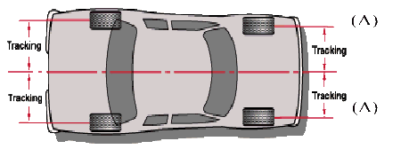
A) the steering track rods converge towards the centre of the rear axis,
B) the axis passing through the rear wheels (regardless of whether they are toe-in) are symmetrical in relation to the front wheels,
C) the steering track rod, steering box. and steering return are in mid position,
D) the adjustable track rods are of the same length,
E) the steering wheel is in a symmetrical position,
When the direction is centred, the steering geometry is perfect and symmetrical, whether turning to the left or right, the same applies in relation to the maximum turn limits of the wheels,
As direction centring involves a large number of parts of the vehicle, both in straight line travel and on bends, and then it is a very important factor to be verified,
Axis deviation
The theoretical condition in which the projection of the front wheels on the rear axis is symmetrical, the steering wheel and the steering mechanism are at the centre of their movement range and the adjustable track rods are of symmetrical length, this cannot always be respected due to the occurrence of deformations or deviations to the axis caused by bumps of varying intensity, These deviations can be grouped into three class types, although there are some types of deviations which can only be identified and rectified by using systems linked to the frame and, or, chassis,

1) the front axis is oblique in relation to the longitudinal axis of the vehicle, because of the resistance to forward travel met with by the directional wheels, these will put themselves into a symmetrical position in relation to the rear axis, naturally, this is assuming that the wheels are linked by the steering track rod system,
On the road, it may occur that the steering wheel and the steering are moved from the centre of their total movement range, in order to recover the steering centre, it is necessary to shorten one adjustable track rod and lengthen the other one, which will straight away deform the steering parallelogram,
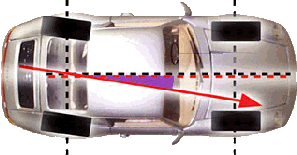
However, when the axis deviation exceeds 1 degree, then the steering geometry is inevitably affected the rear axis is oblique in relation to the longitudinal axis to a value of (A) on the road, the front wheels put themselves into a symmetrical position with their projections to the rear wheels (A) and (A) equal, which means that the track rods, the steering centre and the steering wheel centre are also regular,

In this case, the rear wheels undergo a negative drift (UK) respectively, causing irregular wear, this direction orientation is valid so long as the angle (B) does not exceed 30’ after which the vehicle becomes sensitive to the thrust factor, expressed by the ratio,
 (B) (B)
Drive Thrust
Vehicle weight
If this ratio is high, the directional wheels go to an angle position that is symmetrical with the new axis (and no longer to the wheels) created by the rear wheels in the way described in the following case,
This variation occurs to the detriment of the steering centre and the steering wheel centre, and it is impossible to compensate as it is dynamic, this characteristic effect can be perceived on the road when, under the effect of active engine thrust, the steering wheel changes its orientation by itself,
There is a transverse, non oblique deviation between the two axis,
The front wheels go to a symmetrical angle (%) that is no longer in relation to the rear wheels, but to their axis, which means that, on the road, the front wheels are in the condition of least resistance,
The exception to this directional attitude condition can occur when, because of an irregular weight distribution on the ehicle, a force couple is created which causes the front wheels to turn, to the detriment of the steering centre and the steering wheel centre.
|